N-Type connectors are designed to satisfy the need for a durable, weatherproof, medium-size RF connector with consistent performance through 11 GHz. Our N-Type connectors feature threaded coupling mechanisms and are fully interchangeable with N-Type connectors made to the MIL-C-39012 specification. These connectors are used in all systems where excellent RF and mechanical performance is critical.
Related Products
FEATURES AND BENEFITS
Broad line of military, industrial and commercial grade products available
Excellent RF performance from DC to 11 GHz
Threaded coupling mechanism ideal for vibration resistance
APPLICATIONS
Antennas
Base stations
Instrumentation
Satellite systems
WLAN
Radar systems
Broadcast
Surge protection
N-TYPE SPECIFICATIONS
| Electrical | |
| Impedance | 50 Ohm |
| Frequency Range | 0-11 GHz |
| VSWR | |
| M30912 Straight Connectors 0-11 GHz | 1.30 Max |
| M30912 Right Angle Connectors 0-11 GHz | 1.35 Max |
| Dielectric Withstanding Voltage | 2500 VRMS |
| Voltage Rating | 1500 volts peak |
| Insulation Resistance | 5000 MΩ min |
| Contact Resistance | |
| Outer Contact | 0.2 mΩ |
| RF Leakage | -90 dB min @ 3 GHz |
| Insertion Loss | 0.15 dB max @ 10 GHz |
| Environmental | |
| Temperature Range: | |
| TFE Insulation | -65⁰C to +165⁰C |
| Copolymer of Styrene | -55⁰C to 85⁰C |
| Weatherproof | All series N with gaskets are weatherproof |
| Hermetic Seals | Pass helium leak test of 2 x 10⁻⁸ cc/sec |
| Pressurized Shock | Compressed seal Mil-STD-202, Method 213 |
| Vibration | Mil-STD-202, Method 204 (test cond. D) |
| Moisture Resistance | MIL-STD-202 Method 106 |
| Corrosion | Mil-STD-202, Method 101 ( test cond. B) |
| Temperature Cycling | Mil-STD-202, Method 102 (test cond. D) |
| Altitude | MIL-STD-202 Method 105 (test cond. C) |
| Mechanical | |
| Mating | 5/8-24 threaded coupling |
| Cable Affixment (Braid or Jacket): | |
| All Crimps | Hex braid crimp |
| Clamps | Screw-thread nut and braid clamp |
| Cable Affixment (Center Conductor): | |
| Crimps | Crimp or solder |
| All Others | Solder only |
| Captivated Contact: | |
| All Crimps | Yes |
| Others | Where specified |
| Cable Retention | |
| Crimps | 60-120 lbs |
| Clamps | 30-70 lbs |
CORRUGATED TYPE N SPECIFICATIONS
| Electrical | |
| Impedance | 50 Ohm |
| Frequency Range | 11.0 GHz |
| Return Loss (Freq. GHz) | |
| 1-2GHz | 33 dB |
| 2-3GHz | 28 dB |
| Operating Voltage | 707 VRMS max |
| Dielectric Withstanding Voltage | 2000 VDC |
| Peak Power | 10kW max |
| Avg. Power | .60kW maz |
| Insulation Resistance | 5000 MΩ |
| Shielding Effectiveness | 125 dB min |
| 3rd Order IM Product, typical | -125 dBm (-168 dBc) |
| Insertion Loss | .05 freq GHz |
| Environmental | |
| Temperature Range | |
| Operating | -40⁰C to +150⁰C |
| Storage | -70⁰C to 100⁰C |
| Thermal Shock | Mil-STD-202, Method 107 (test cond. A) |
| Immersion | IEC 529, IP68 |
| Vibration | Mil-STD-202, Method 204 (test cond. B) |
| Corrosion | Mil-STD-202, Method 101(test cond. B) |
| Mechanical Shock | MIL-STD-202 Method 213 (test cond. I) |
| Mechanical | |
| Mating | MIL-STD-348 |
| Inner Attachment Method | Solder or Captivated |
| Outer Attachment Method | Compression |
| Assembly Torque | 18/22 lb-ft (25/30 N-m) |
| Coupling Torque | 15.00 lb-in (1.70 N-m) |
| Coupling Nut Retention Force | 100.00 lbs (444.80 N) |
| Connector Durability | 500 cycles, 12 cycles/min |
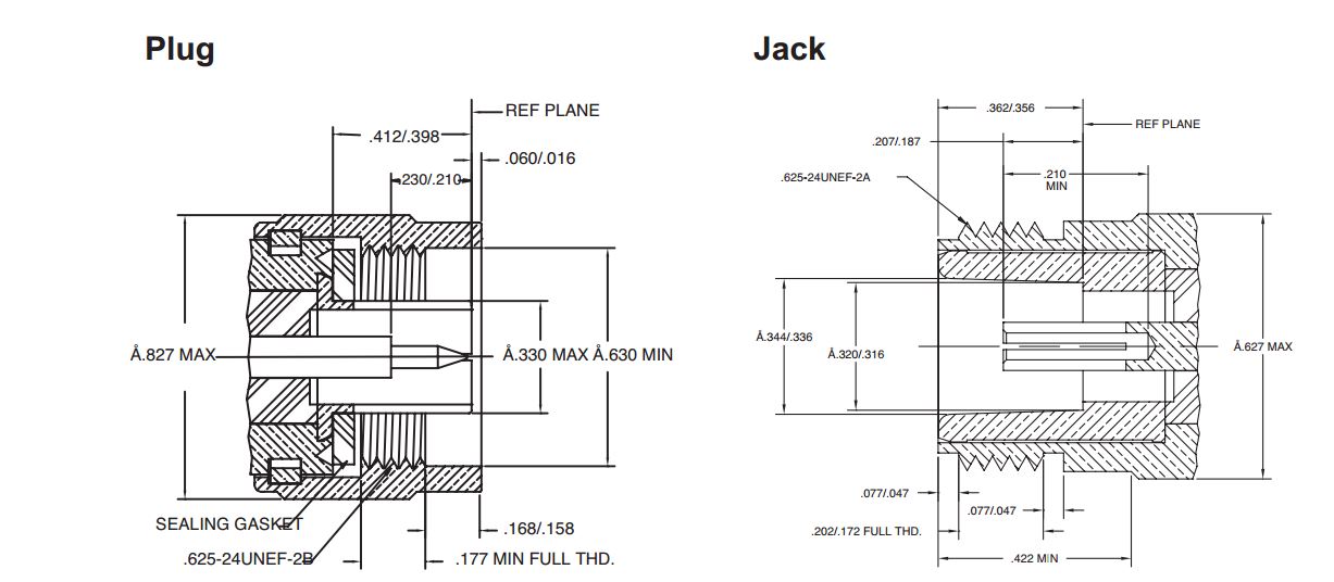
INTERFACE DIMENSIONS